
Why Reciprocating Compressors Dominate High-Pressure Oxygen Service
Among all compressor technologies, the reciprocating (piston) design has the longest operational history in oxygen service and remains the preferred choice for applications requiring pressures above 50 bar. The mechanical simplicity of a piston compressor — a piston moving back and forth in a cylinder — translates to predictable wear patterns, field-serviceable components, and a well-understood failure mode profile that allows preventive maintenance to be scheduled and executed reliably.
For an oxygen reciprocating compressor, the design modifications required for safe oxygen service are well-established: oil-free piston rings of PTFE or PCTFE, oxygen-compatible valve materials (Monel or stainless), thorough oxygen-clean assembly procedures, and multi-stage intercooling to control discharge temperatures. These modifications add cost and complexity compared to a standard air reciprocating compressor, but the result is a machine capable of reliably and safely compressing pure oxygen to 350 bar and beyond.

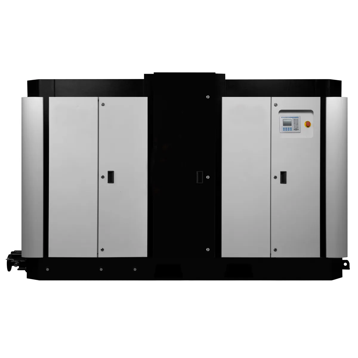
Industrial oxygen reciprocating compressor with four-stage configuration for cylinder filling service
Operating Principle of the Oxygen Reciprocating Compressor
The oxygen reciprocating compressor operates on the principle of positive displacement: a piston moving within a precision-bored cylinder traps a fixed volume of gas, compresses it by reducing the cylinder volume, and discharges it through a one-way outlet valve when the required pressure is reached.
| Phase | Description |
|---|---|
| Suction phase | Piston moves away from cylinder head (down or outward). Suction valve opens when cylinder pressure falls below inlet pressure. Oxygen enters the cylinder. |
| Compression phase | Suction valve closes. Piston moves toward cylinder head. Trapped oxygen is compressed. Pressure and temperature rise. |
| Discharge phase | Discharge valve opens when cylinder pressure equals downstream pressure. Compressed oxygen flows out. Piston reaches top of stroke (TDC). |
| Clearance expansion | Small trapped volume at TDC re-expands as piston begins suction stroke. This reduces volumetric efficiency — minimizing clearance volume improves efficiency. |
| Multi-stage operation | Discharge from Stage N passes through an intercooler, then becomes the suction for Stage N+1. Each stage increases pressure while intercoolers keep temperature manageable. |
Industrial Sizing Guide for Oxygen Reciprocating Compressors
Sizing an oxygen reciprocating compressor for industrial service follows a structured methodology. Errors in sizing lead either to undersized machines that cannot meet demand or to oversized machines with higher capital and operating costs than necessary.
Step 1: Define the Duty Point
Establish the required oxygen flow rate (Nm3/h), inlet conditions (pressure, temperature, purity), and discharge pressure. The duty point is the combination of these parameters under the worst-case operating conditions — typically maximum ambient temperature and maximum demand.
Step 2: Calculate Compression Ratio
Overall compression ratio = Pdischarge / Pinlet (absolute pressures). This determines the minimum number of stages. Each stage compression ratio should not exceed 4:1-5:1 for oil-free oxygen service due to temperature limitations.
Step 3: Stage Temperature Check
Calculate the theoretical adiabatic discharge temperature for each stage: T2 = T1 x (P2/P1)^((gamma-1)/gamma) where gamma = 1.4 for oxygen. Ensure T2 does not exceed 150 degrees C before intercooling. If it does, add more stages.
Step 4: Power Calculation
Theoretical isothermal power per stage = Q x P1 x ln(P2/P1). Real shaft power = theoretical x 1/(stage efficiency). Sum all stages for total shaft power. Add drive losses for motor selection.
Step 5: Select Cylinder Configuration
Single-acting or double-acting cylinders. Horizontal, vertical, or L-shaped frame arrangements. Bore and stroke selection to achieve required displaced volume at the operating speed.
Step 6: Verify Duty Margin
Add 10-15% capacity margin to the calculated requirement to allow for sieve bed aging (in PSA service), ambient condition variation, and future demand growth.
Engineering team sizing oxygen reciprocating compressor for new PSA cylinder filling plant
| Application Scale | Duty Point | Stages | Power Range | Frame Type |
|---|---|---|---|---|
| Small industrial | 1-5 Nm3/h at 200 bar | 2-3 stage | 5-15 kW | Single-cylinder or V-configuration |
| Medium industrial | 5-20 Nm3/h at 200 bar | 3 stage | 15-60 kW | Multi-cylinder horizontal balanced opposed |
| Large industrial | 20-100 Nm3/h at 200 bar | 3-4 stage | 60-300 kW | Large frame horizontal balanced opposed |
| High-pressure specialty | 1-10 Nm3/h at 350 bar | 4 stage | 10-60 kW | Small-bore high-pressure cylinders |
Explore Our Full Product Range
Leading manufacturer of oil-free air compressors for oxygen, medical, and industrial applications
Maintenance Planning for Oxygen Reciprocating Compressors
The reliability of an industrial oxygen reciprocating compressor depends entirely on the quality of the preventive maintenance program. Unlike scroll compressors with few moving parts, reciprocating machines have multiple wear components that require scheduled inspection and replacement to maintain performance and safety.
Piston Ring Replacement
PTFE piston rings and rider rings are the primary wear component in oil-free oxygen reciprocating compressors. Replacement intervals of 4,000-8,000 hours are typical, depending on pressure, temperature, and inlet gas cleanliness. Worn rings cause reduced volumetric efficiency and increased discharge temperature.
Valve Inspection and Replacement
Inlet and discharge valves in each cylinder should be inspected at every piston ring change and replaced when wear, cracking, or carbon deposits are found. Valve failure is the most common cause of unplanned oxygen reciprocating compressor downtime.
Cooler Cleaning
Intercoolers and aftercoolers accumulate fouling on both the gas and cooling medium sides over time. Annual internal cleaning of coolers maintains heat transfer efficiency and prevents excessive discharge temperatures.
Performance Trending
Recording stage pressures, temperatures, current draw, and flow rate at regular intervals allows early detection of developing problems. A rising stage discharge temperature typically indicates worn rings or valves before complete failure occurs.